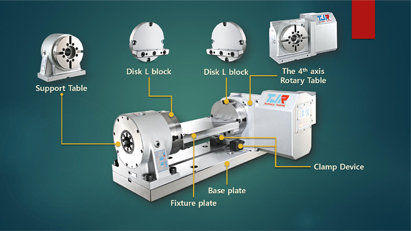
A support table is used to support the outboard end of a part or fixture, ensuring stability during machining operations. The center height of the support table must match the center height of the rotary table to ensure proper alignment.
The type of support table you need depends on your specific application. Support tables can either have a simple bearing setup or come equipped with a pneumatic or hydraulic brake system. If machining will occur on the side of the part or fixture being supported, a model with a brake system is recommended. The brake system on the support table is typically connected to the rotary table's brake system, activating simultaneously when the rotary table's brake is engaged. For instance, if the rotary table uses a pneumatic brake, the support table should also have a pneumatic brake. Similarly, a hydraulic brake on the rotary table should be paired with a hydraulic brake on the support table.
To calculate the total braking force for the system, combine the brake force from both the rotary table and the support table. The provided image illustrates the role of the support table within the classic trunnion system of a 4th axis rotary table, showing how it integrates into the entire setup.
TJR rotary tables can be mounted vertically or horizontally, depending on the machine type and machining purpose.
On Vertical Machining Centers (VMCs), vertical mounting serves as an A/B-axis, while horizontal mounting functions as a C-axis. This allows the rotary table to adapt to different machining angles and workpiece requirements.
On Horizontal Machining Centers (HMCs), the rotary table is typically mounted on the B-axis pallet within the machine’s available swing capacity, ensuring stable operation and proper clearance during machining.
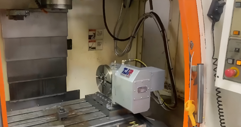
Example of the 4th Axis Rotary Table Mounted in the Vertical Position as an A-axis on a VMC
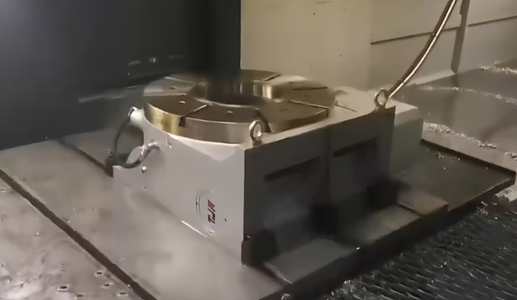
Example of a 4th Axis Rotary Table Mounted in the Horizontal Position as a C-axis on a VMC
The fastest way to determine whether a 4-axis rotary table is suitable for vertical or horizontal installation is to check the motor cover direction.
TJR uses four standardized motor orientations—R, N, B, and L types—to help users quickly understand installation compatibility and interference conditions.
| Type | Description | Illustration | Applicable Mounting Position | ※Symbol in the catalog |
|---|---|---|---|---|
| R Type | Right-side motor cover | 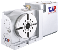 RC-170R |
Suitable for vertical or horizontal positions |  |
| N Type | Compact right-side motor cover | 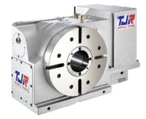 RC-255N |
Suitable for vertical position only |  |
| B Type | Back-side motor cover | 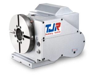 AR-210B |
Suitable for vertical position only | |
| L Type | Left-side motor cover | 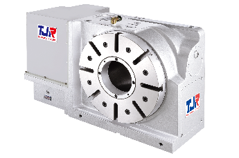 RC-320L |
Suitable for vertical or horizontal positions | |
These motor cover designations serve as a quick visual reference, enabling users to determine the appropriate mounting orientation without requiring detailed structural analysis.
To help users quickly understand installation direction without checking technical drawings, TJR provides clear orientation symbols in all rotary table catalogs.
These symbols indicate whether a model supports vertical installation, horizontal installation, or both.
| Description | Symbol |
|---|---|
| Vertical only(4th axis) | |
| Horizontal only(4th axis) |  |
| Horizontal only(4th axis) | |
| Vertical & Horizontal(5th axes) |  |
These orientation symbols provide a quick visual guide to help users identify the rotary table installation direction, without the need for in-depth structural interpretation.